
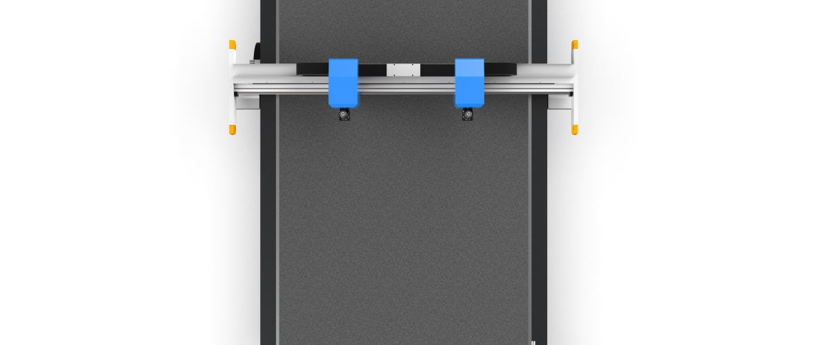
What is a film proofing machine?
A film proofing machine is a CNC device specifically designed for cutting and proofing film materials, commonly used in packaging, electronics, automotive interiors and other industries. It cuts film using a high-frequency oscillating blade (approximately 18,000-25,000 times per minute), requires no molds, and can output samples directly from CAD files, greatly shortening the proofing cycle. Compared with laser cutting, the film proofing machine does not produce burnt edges, making it especially suitable for heat-sensitive films such as PET, PVC, and TPU.
Core Parameters and Selection Points
1. Cutting Accuracy and Repeat Positioning Accuracy
The proofing stage has high precision requirements; typically, cutting accuracy should reach ±0.1mm, with repeat positioning accuracy of ±0.05mm. For electronic films (such as FPC coverlay), it is recommended to choose models with accuracy within ±0.05mm. Note the distinction between static accuracy and dynamic accuracy, as actual cutting is affected by the material fixing method and tool wear.
2. Cutting Thickness Range
Common film proofing machines have a cutting thickness of 0.05-2mm (depending on material hardness). For example: PE film can reach 1.5mm, while PET film usually does not exceed 0.5mm. If thicker materials need to be cut (such as 3mm or more), a high-power oscillating knife or a multi-pass cutting function must be used.
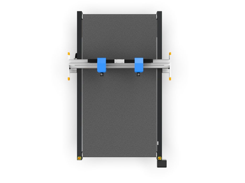
3. Table Size and Material Fixing Method
The table size should be selected according to the commonly used proofing working area; common specifications include 600×400mm, 900×600mm, and 1300×900mm. The material fixing method directly affects cutting quality: vacuum adsorption tables are suitable for most films. For ultra-thin films (<0.1mm), it is recommended to choose a table with zoned adsorption or electrostatic adsorption to prevent material displacement.
4. Tool system
Film proofing machines are usually equipped with a variety of tools: oscillating knife (general purpose), round knife (suitable for continuous curve cutting), drag knife (suitable for thin materials), and punch knife (for drilling). When selecting, pay attention to the convenience of tool changes and whether automatic tool setting is supported. For multi-layer film cutting, a pneumatic oscillating knife can be selected for greater cutting force.
5. Software compatibility
Ensure the equipment supports common CAD formats (DXF, DWG, AI, PDF) and direct import functionality. Some models come with built-in nesting software that can optimize material utilization. It is recommended to choose an open and upgradeable software system to facilitate subsequent integration with production systems.
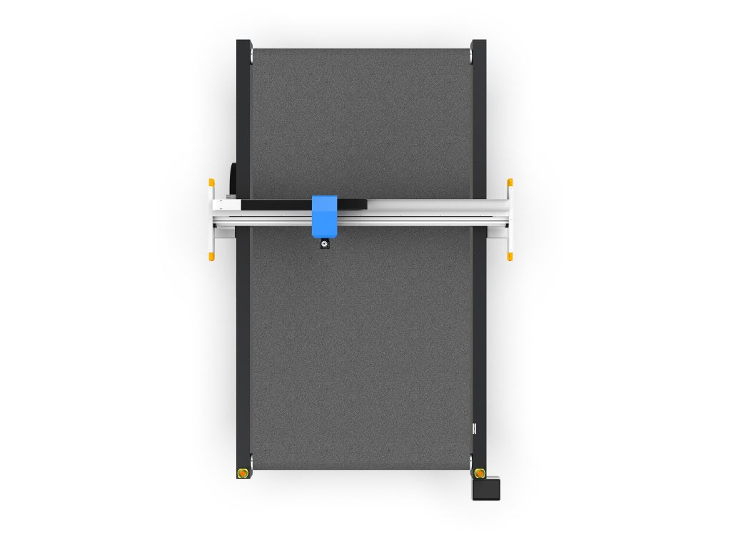
Operating Procedure and Practical Tips
1. Material Preprocessing
Before cutting, the film must be placed flat to avoid wrinkles. For roll materials, it is recommended to use an unwinding device and maintain appropriate tension (usually 5-20N, adjusted according to material thickness). Keep ambient humidity at 40%-60% to prevent static electricity from causing the material to attract debris.
2. Parameter Settings
Key parameters include: cutting speed (usually 200-800mm/s), vibration frequency (18,000-25,000 times/min), knife pressure (0.1-0.5MPa). It is recommended to perform a small sample test cut first and observe the cut edge quality. For example, when cutting 0.2mm PET film, set the speed to 400mm/s and the knife pressure to 0.2MPa to obtain a smooth cut edge.
3. Knife Maintenance
Regularly check blade wear; typically the blade needs to be replaced after cutting 10-20 kilometers (depending on material abrasiveness). When cutting films containing glass fiber or fillers, wear accelerates, so the replacement interval should be shortened. Avoid collisions when storing blades and keep the cutting edge sharp.
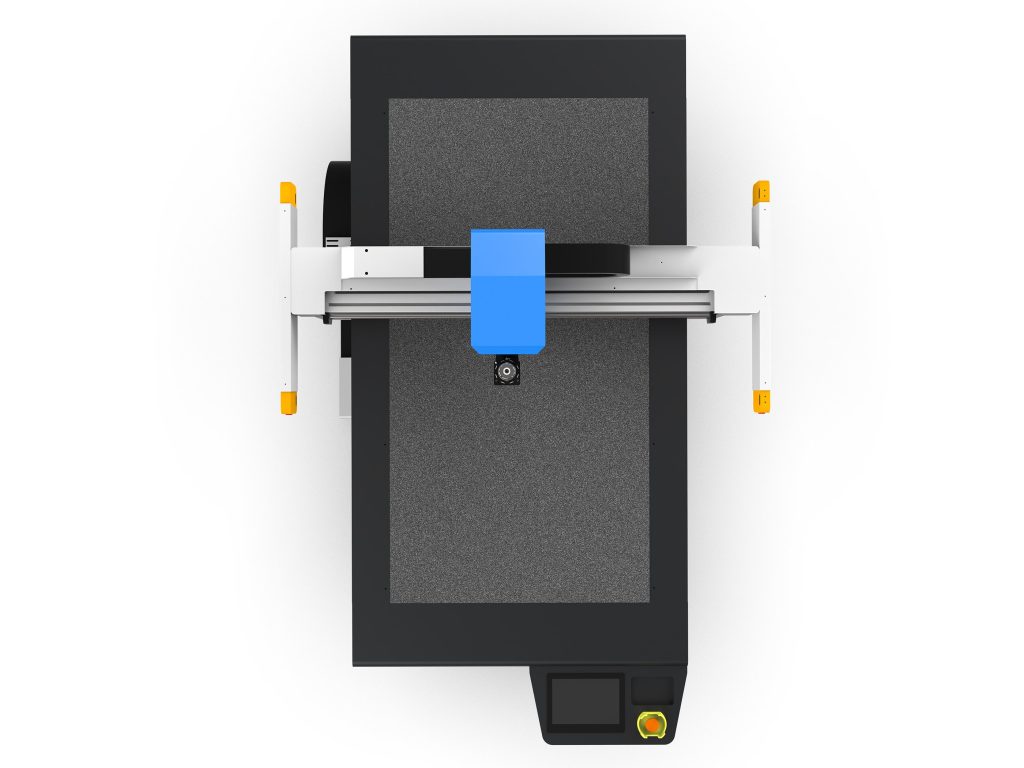
4. Common problems and solutions
- Rough cut edges: Check whether the blade is worn, reduce the cutting speed or increase the vibration frequency.
- Material shifting: Increase the vacuum suction force, or use double-sided tape to secure the edges.
- Incomplete cutting: Increase the knife pressure or reduce the speed, and check whether the blade tip protrudes enough (usually 0.5-1mm).
- Static adsorption: Install an ion blower and maintain ambient humidity.
Application Scenarios and Selection Recommendations
Film proofing machines are widely used in:
- Packaging industry: Labels and flexible packaging bag samples, commonly choose 600×400mm table, accuracy ±0.1mm.
- Electronics industry: FPC cover film and insulating film, requiring accuracy ±0.05mm with CCD vision alignment function.
- Automotive interiors: Dashboard film and decorative film, requiring large working area (1300×900mm and above) and automatic feeding system.
- Medical industry: Medical films and dressings, requiring clean environment, optional stainless steel table models.
When selecting a model, it is recommended to bring actual materials to the supplier for trial cutting to evaluate cut edge quality, efficiency, and ease of operation. Also consider equipment expandability, such as whether modules like CCD and automatic feeding can be added.
Maintenance and Care
Clean the table and guide rails daily, check the pneumatic filter weekly, and lubricate transmission components monthly. During prolonged shutdown, release the blade clamping device to avoid spring fatigue. Establish a maintenance log to record blade replacements and parameter adjustments for traceability of quality issues.
As the core equipment in the proofing process, the film proofing machine can significantly improve sample quality and development efficiency through proper model selection and correct use. We hope this guide can provide a reference for your decision-making.