
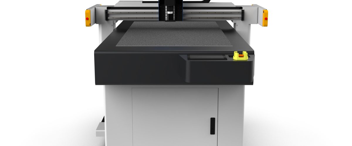
Core Parameters of Carbon Fiber Cutting Machines
Carbon fiber composites are widely used in aerospace, automotive manufacturing, and sports equipment due to their high strength-to-weight ratio. Achieving precise cutting requires specialized equipment—the carbon fiber cutting machine. Its core performance parameters directly affect cutting quality and production efficiency.
Cutting Accuracy: Within ±0.1mm
Precision carbon fiber cutting machines use closed-loop servo control systems combined with high-resolution encoders (resolution up to 0.001mm), ensuring positioning errors remain within ±0.1mm. For example, model DNC-800F features a 4-axis linkage system, enabling complex contour cutting, suitable for carbon fiber fabrics or prepregs with thicknesses of 1–6mm.
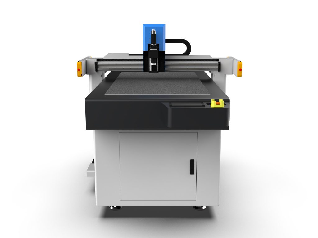
Tool System: Dual Oscillating High-Speed Rotary Cutter Head
Standard configuration includes a tungsten carbide alloy blade with a diameter of 150mm and a rotational speed of up to 8000rpm. The blade edge angle is designed at 12° to minimize material tearing. Optional diamond-coated cutter heads extend service life to over 2000 hours, particularly ideal for high-hardness carbon fiber/epoxy composite materials (e.g., T700/T800 grade).
Working Table: Vacuum Adsorption + Pneumatic Clamping
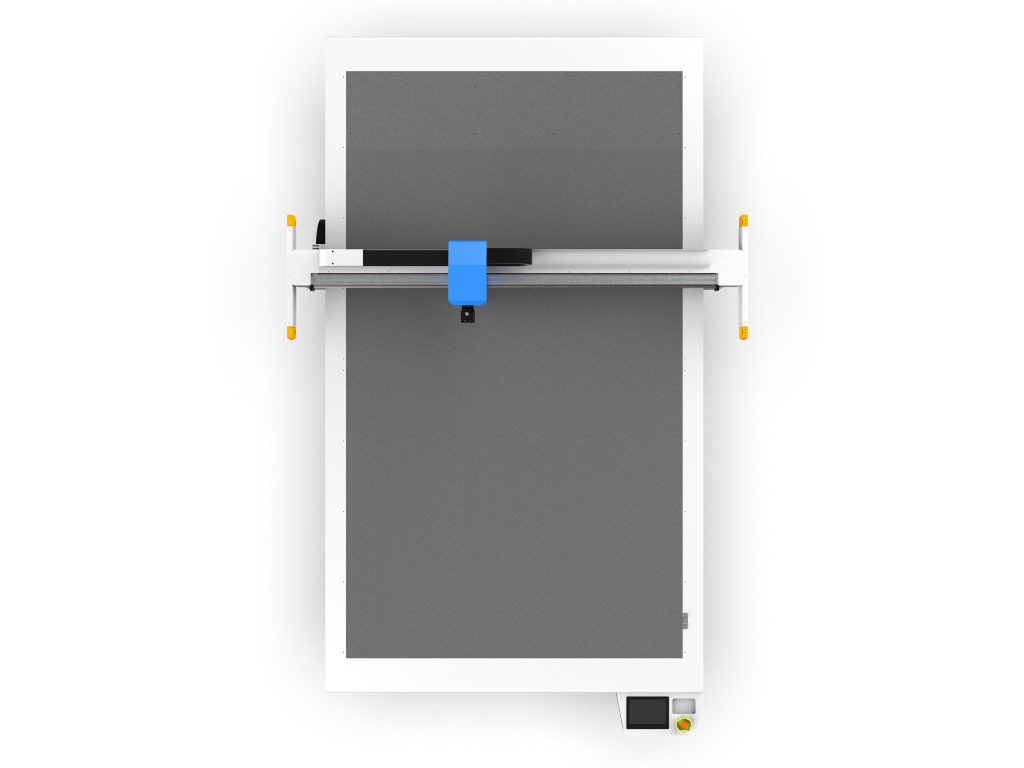
The worktable uses 304 stainless steel panels equipped with a vacuum adsorption system featuring 200 individually controlled air holes, achieving a maximum negative pressure of -90kPa. Combined with pneumatic clamping (pressure range 0.4–0.6MPa), it effectively prevents material displacement or curling during high-speed cutting, especially suitable for large sheets measuring 1200mm wide by 2000mm long.
Cutting Speed and Power
Typical cutting speed ranges from 50 to 300mm/min, automatically adjusted based on material thickness and layer count. For instance, when cutting a single 3mm-thick carbon fiber plate, a recommended speed of 150mm/min is advised; for stacked layers (≤8 layers), reduce the speed to 80mm/min to avoid burrs. The entire machine’s motor power is 7.5kW, equipped with a frequency inverter, with a response time under 20ms.
Key Operational Techniques in Practical Applications
Material Pre-treatment: De-oiling and Flattening
Residual mold release agents or oils on carbon fiber surfaces can reduce tool life and cause adhesion issues. After wiping with isopropyl alcohol, allow the material to rest in a constant temperature and humidity environment (23±2°C, relative humidity 50±5%) for no less than 4 hours before loading. For roll materials, use a tension roller system to straighten them, maintaining tension between 5–8N.
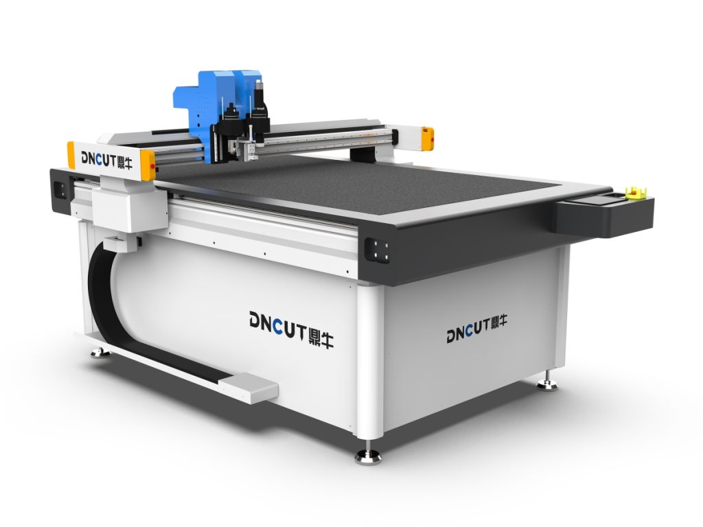
Tool Maintenance: Regular Replacement and Alignment
Inspect blade wear after every 500 square meters of cutting. Replace blades immediately if visible chipping or blackened cut edges appear. Alignment procedure: Use a 0.02mm feeler gauge to check the gap between the cutter tip and the worktable surface, adjusting it to 0.05±0.01mm. Perform tool center calibration at least once per month.
Program Optimization: Path Planning and Feed Strategy
In the CNC system, set a “segmented feed” strategy: start with 50% rated speed for initial rough cutting, then switch to full-speed cutting after completing the contour. For internal holes or narrow slots (width <10mm), enable "zigzag feed" mode to reduce stress concentration. Simultaneously activate the "thermal compensation" function to automatically correct coordinate deviations based on ambient temperature changes.
Frequently Encountered Issues and Solutions
- Severe Burr Formation: Check blade sharpness and confirm whether cutting speed is too fast; recommend reducing speed by 30% and increasing idle travel distance (≥5mm).
- Material Delamination: Inspect vacuum adsorption uniformity and verify sufficient clamping pressure; replace sealing gaskets if necessary (recommended replacement every quarter).
- Abnormal Tool Wear: Analyze material composition—if glass fibers are mixed in, switch to diamond-coated cutter heads; also inspect cooling system for blockages.
Safety Protection Standards
The equipment must be fitted with a laser-sensitive safety door (response time ≤50ms) and dust collection devices in the cutting area (filtration precision ≤1μm). Operators must wear dust masks (N95 or higher), safety goggles, and anti-static gloves. Manual debris removal is strictly prohibited while the machine is running.
Selection Recommendations: Matching Models to Application Scenarios
For small-batch custom parts (e.g., drone wings), choose the desktop model DNC-500E with a maximum working area of 500mm, supporting manual teach-in programming. For continuous production lines (e.g., electric vehicle battery pack casings), recommend the industrial-grade DNC-1200X, featuring automatic loading/unloading interfaces (compatible with robotic integration), capable of handling sheet sizes exceeding 1000×2000mm.